All posts by ndunlevy

Taxes, Death, and Cracks in Stucco Walls


As an exterior cladding material, Portland cement plaster, or stucco, is a versatile material and used in traditional, modern, and contemporary designs. It can provide either an ornate or simple, clean look. But, as the old adage goes, “there are three things in life you can count on …” and the most reliable of these is that when stucco hydrates, it shrinks and hairline cracks form. Regardless of design style, if you design with stucco, it is absolutely imperative to understand how it performs and why.

Whether you specify a traditional three-coat application or a one- or two-coat modified polymer system, understanding the basics of Portland cement plaster design and installation will ensure that you get the aesthetics and performance results right, including the building code requirements often found in reference standards and industry best practices.

How to Patch Stucco

According to doityourself.com, cracks are quick and easy to fix. Small cracks can be filled simply with a coat of paint, while thicker cracks may be cauked.  Meanwhile, very large cracks and holes require more attention. You will need to clear out the damaged portion of the stucco and then carefully refill it with several applications of new stucco, while replacing damaged mesh or tar paper if needed.

The total thickness of 7/8 in. for three‐coat work is required, in accordance with ASTM C926. While the adage of “all stucco cracks” is generally true, the use of reinforcing mesh or fibers in the plaster, along with correct placement of control joints, can help mitigate cracking. Hot weather and accelerated drying time can also contribute to cracking, thus curing of the stucco is important in these conditions. Controlling cracks in stucco means fewer callbacks for the contractor, lower maintenance cost, and enhanced curb appeal.

Stucco and the Weather

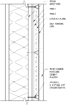
As another old adage goes, “the best offense is a good defense.” Proper care and preparation of stucco can help reduce the need for stucco repairs later on. The majority of stucco walls, whether traditional hard‐coat or proprietary systems, are installed on metal lath over wood or metal stud construction. As such, they are designed as drainage plane walls with metal lath over a water‐resistive barrier (WRB).

Stucco requires weather barrier behind the lath to control the penetration of water. The paper must be continuous and properly shingled over each sheet and accessories to direct the flow of water. The weather barrier gets wet during application of the stucco and, after drying, pulls away from stucco, creating the drainage plane.

Best industry practices are to use a rainscreen system, incorporating a drainage mesh between the WRB and the lath. The basic components of the wall and their requirements can be found here.

The selection, installation, and protection of the WRB are the most critical components in the weather‐resistance of the wall. The WRB should be installed with cap nails, screws, or wide crown staples; slap staples can tear the barrier and should not be used. Care should be taken to seal wall penetrations and protect the WRB. When installation of multiple layers of WRB is required, each layer shall be installed in an independent manner so that each layer provides a continuous drainage plane.

Building wrap and fluid‐applied WRBs have increased in popularity and are accepted by building officials as an alternate material to asphalt felt. The Code requires that these types of WRBs be installed in accordance with the manufacturer’s installation instructions, which may include taping of joints of sheet material, when used as an air‐barrier. If two layers are required, local codes may also require a specific layering pattern.

PC Plaster

STUCCO REPAIRS: IN THE COLD

According to cement.org, “the temperature of newly applied stucco should be maintained at a minimum of 40 degrees Fahrenheit. In many cases, this can be achieved by heating the structure and covering the exterior surfaces.”

For temperatures lower than that, the ingredients themselves can be heated before mixing the plaster. Water and sand are good at holding heat due to their mass, although water is simpler to heat up. If it comes to it, both can be heated and used to provide some extra protection when performing stucco repairs in cold weather. To avoid problems such as flash set of the plaster, though, cement.org does advise that “fresh mixtures should not be heated to temperatures exceeding 120 degrees Fahrenheit.” Additionally, the concrete should be kept from freezing for at least two days following its application, since any excess water will expand and your wall will begin to crack … before it has even had time to set.

STUCCO CONCRETE BASICS

Stucco is a traditional exterior finish material, typically three coats of Portland cement plaster, applied over weather barrier to create a drainage plane wall system. It is impact‐ and fire‐resistant; and because it is applied in a plastic state, it can be made to conform to virtually any shape. Durable stucco is, however, highly dependent on knowledgeable and skilled application, as many of the problems attributed to stucco (e.g., cracking, delamination, water leakage) are not inherent to the product but are the result of improper installation.

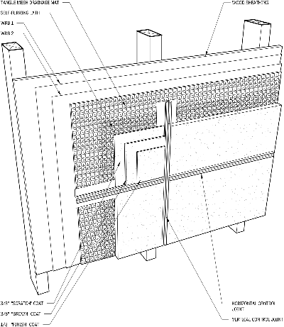
Stucco is applied in three coats: scratch, brown, and finish.

  • The scratch and brown coats are Portland cement plaster, typically each approximately 3/8‐in. thick; together they are called the base coat. The base coat must be moist‐cured for two days, then further curing of five days before application of the finish coat. In very hot or windy conditions, it may be necessary to protect the base coat with tarps or sheeting. The scratch coat is so‐called because, after application, the surface is roughened with a rake or other device to promote a mechanical bond of the brown coat.
  • The brown coat is applied after the scratch coat has set up. IBC requires a minimum or 24 hours between coats if damp‐curing is used, or 48 hours without. In the recent past, one week was common for curing. It is important that the scratch coat be properly cured before the application of the brown coat, to minimize the cracking. The brown coat may be reinforced with a variety of fibers, and it must be trowel‐floated while still moist but after taking an initial set, to densify the surface and further reduce cracking. Application of the brown coat before the scratch coat has properly cured, and failure to make the additional trowel‐float pass, are common causes of cracking in the finished stucco.
  • The finish coat may be either Portland cement plaster or acrylic, typically 1/8‐in. thick. Portland cement‐based finish coats are likely to be more durable, but acrylic finish coats generally have better color consistency. Factory‐mixed finish coat mixes improve color consistency of cement‐based finish coats.

PC Plaster

Current subscribers, to understand more about the performance of Portland cement plaster, check out the latest update to AGS Online,Taxes, Death, and Cracks in Stucco Walls.” (Log in required to view)

Not a subscriber? Sign up here

Managing Movement in Clay Masonry


While the great debate wages over the terms “expansion joints” vs. “control joints,” no one denies that they are both forms of “movement joints” and are necessary to prevent cracking in clay masonry veneer walls. Thus, it is important to understand the types of movement in clay-based masonry veneer walls and how to control the cumulative effects through the proper design of movement joints.

It has been said, “either you or nature will decide where to locate masonry movement joints, either way they will occur.” And while architects tend to like straight, clean lines for building movement, nature is not so particular. Unplanned movement in masonry walls often results in broken masonry units, unsightly cracks, and water intrusion into the building.  Movement occurs both vertically and horizontally and occurs at different rates in dissimilar materials. Good design of movement joints requires the aesthetic placement of joints in locations necessary to accommodate anticipated movement.

DESIGNING WITH MASONRY MOVEMENT JOINTS

In order to accommodate for the total unrestrained movement of brick veneer, movement joints must be designed into the wall. The placement of these joints generally takes into consideration both the art and science of building design and functional aspects. The designer must consider building geometry (height, length, offsets in walls), materials, fenestrations, and building structural system. Brick veneer walls may include both horizontal and vertical joints, joints at dissimilar materials, and joints around wall penetrations.

The building code prescribes a maximum supported height for anchored veneer masonry without an engineered design. This is typically about 30 ft. above the foundation or every two floors. Brick veneer is generally supported on steel shelf angles and provision for movement is provided immediately below the shelf angle. This includes a minimum ¼‐in. compressible material and a sealant joint. Some owners and designers object to large horizontal movement joints; lip brick may be used to minimize the apparent size of the joint.

Movement Joint

RULES AND RECOMMENDATIONS FOR PLACING MOVEMENT JOINTS

Rules

  • Align with building expansion joints
  • Align with changes in backup assembly
  • Sufficient number of joints to accommodate the total unrestrained movement of brick veneer

Recommendations

  • Change in materials (differing thermal expansion coefficient)
  • Near building corners (generally within 24 in.)
  • Offsets in walls
  • Every 20 to 24 ft. horizontally in straight wall runs
  • No more than 15 ft. in parapet walls and locations where the masonry is subject to greater climate exposure

TYPES OF MOVEMENT JOINTS

Masonry Construction magazine offers a summary of the difference between “control joints” and “expansion joints”, which can be boiled down to this:

“A control joint is a continuous vertical joint filled with mortar, but with a bond breaker on one side so that tensile stress cannot develop across the joint … An expansion joint is a continuous vertical or horizontal joint, left completely free of mortar and filled with elastomeric sealant to keep it watertight.”

The difference, while subtle, is important to understand when planning out any brick veneer wall.

WHY MOVEMENT JOINTS ARE NEEDED

Building materials expand and contract based upon their design coefficient of thermal expansion. Differing materials are also subject to long‐term expansion or contraction due to moisture. Clay masonry absorbs moisture and expands while concrete masonry typically hydrates and shrinks. When dissimilar materials are used as part of the exterior cladding, and penetrations through walls of differing materials are subject to different rates of expansion, the wall design must accommodate this movement. Movement can occur at window openings, canopy attachments, precast concrete lintels, stone banding, and other similar areas.

CLAY MASONRY BASICS

Brick and tile are classified according to the specific location where they are used. Standard specifications have been developed to produce uniform requirements for brick. ASTM International publishes the most widely accepted standards on brick. Standard specifications include strength, durability, and aesthetic requirements.

CLAY MASONRY CLASSIFICATION TYPES

TYPE OF BRICK UNIT ASTM DESIGNATION
Building brick C 62
Facing brick C 216
Hollow brick C 652
Paving brick C 902
Paving brick (heavy vehicular) C 1272
Ceramic glazed brick C 126
Thin brick veneer units C 1088
Sewer and manhole brick C 32
Chemical‐resistant brick C 279
Industrial floor brick C 410
TYPE OF TILE UNIT
Structural clay load‐bearing tile C 34
Structural clay non‐load‐bearing tile C 56
Structural clay facing tile C 212
Structural clay non‐load‐bearing screen tile C 530
Ceramic glazed tile C 126

Terms used in each standard for brick classification may include exposure, appearance, physical properties, efflorescence, dimensional tolerances, distortion, chipping, core, and frogs. Brick may be classified by use, grade (exposure), and type (appearance). Properties should be identified. Each ASTM standard has minimum requirements for grade and type, which will be used as the default property if another is not specified.

Specific grades of brick are required to accommodate the various climates in the United States and the different applications in which brick can be used. Brick grades include Severe Weathering (SW), Moderate Weathering (MW), and Negligible Weathering (NW); each is based on the weathering index and the exposure they will receive. The weathering index is the product of the average annual number of freezing cycle days and the average annual winter rainfall in inches (see Figure “U.S. WEATHERING INDEXES”). The exposure is related to whether the brick is used on a vertical or horizontal surface and whether the unit will be in contact with the earth (see Figure “EXPOSURE”). A higher weathering index or a more severe exposure will require face brick to meet the SW requirements. The grades for each specification are listed in Figure “GRADE REQUIREMENTS FOR FACE EXPOSURES”.

U.S. Weathering Indexes

See this page for more.

Complexities of Below-Grade Waterproofing


The below-grade sealing of water intrusion at the building enclosure from the subsoils surrounding the structure should occur at an early stage in many construction projects.

However, the challenges of many below-grade situations are often overlooked and underestimated. Yet, the penalties for making mistakes during this critical step in the sealing process can be severe. Designers should fully understand the different mixtures of below-grade waterproofing materials for each project location and situation.

Since 1932, Architectural Graphic Standards (AGS) has provided architects with the most current design practices and standards. In a fast-paced, competitive industry in which innovation and knowledge is the key to success, AGS Online is able to continuously provide updated technical and design information.

“Below-Grade Waterproofing” is an example of the newest information you’ll find in AGS Online and reflects the current standard of care in building design for this subject. You will find building code considerations, material types, and different methods of achieving a dry building upon final construction.

BELOW-GRADE WATERPROOFING DETAILS

Careful consideration with the selection of the materials and methods specified to achieve the waterproofing results are encouraged during the design as well as field observation stages of the ultimate project. Due to the importance of a waterproofing system, it is most often applied directly to the structure with full contact or adhesion as this method alleviates water travel if a foundation leak is to occur.

Typical below‐grade waterproofing systems are often made up of multiple elements, which include below‐slab and below‐footing vapor barrier, insulation, drain board, foundation drain, waterstops, protection board, filter fabrics, and clean wash stone. Although not all of the aforementioned pieces are required within every system, the designer should carefully consider the ability of the designed system and its prescribed components to not only prevent moisture from penetrating the foundation but to alleviate the hydrostatic pressure imposed upon the system.

Face‐applied waterproofing is often considered standard waterproofing by many as it is the act of applying the waterproofing system to the foundation wall on the exterior (weather) side prior to the backfill of the excavated soils. The waterproofing membrane should continue unbroken from the face of the footing to the top of the footing to above‐grade level, and typically be lapped behind the water‐resistant barrier (WRB) of the above‐grade wall control layer. The remaining layers of the system are installed per the instructions of the manufacturer in order to comprise a tested and complete system. See this diagram for an example of a typical foundation as it relates to below-grade waterproofing.
Foundation Wall Typical System

BELOW-GRADE WATERPROOFING VS. DAMPPROOFING

Although many designers assume that all below‐grade elements to structures with conditioned space within them should be waterproofed, that is not necessarily the case. The International Building Code (IBC) Section 1805, “Dampproofing and Waterproofing” provides the designer guidance as to when foundations should receive which type of treatment. Specifically, Section 1805.2, “Dampproofing” states, “Where hydrostatic pressure will not occur as determined by Section 1803.5.4, floors and walls for other than wood foundation systems shall be dampproofed in accordance with this section.”

Dampproofing is generally provided to reduce or prohibit the absorption of condensation and high‐humidity into below‐grade concrete or masonry and to reduce the likelihood of water not under a head of pressure from moving through or up the construction. Examples of applications requiring dampproofing include on the back side of site retaining walls or at basement walls where there is no head of water. Dampproofing is not “water‐tight” and will not perform to the same levels as waterproofing, and so should not be used in applications that require waterproofing.

SPECIFYING BELOW-GRADE WATERPROOFING

According to a 2005 article from The Construction Specifier, “while there are many excellent systems in the marketplace that can be specified and installed, the key point to success is understanding the benefits and limitations for any particular system.” The article goes on to state that, as is the case for virtually any part of a construction project, good planning and design will pay dividends in the long run. The excavation and replacement of a failed system can be costly in a number of different ways. Warranties, which can run anywhere between five years and 20, should be checked, and “proper design inspection is imperative for all systems no matter what guarantee or warranty is provided.

THE IMPORTANCE OF DRAINAGE IN WATERPROOFING

Keeping water out is obviously tantamount to waterproofing your below-grade space, but a key component of that is helping to keep the water away. As such, proper drainage of the subsoil in and around the foundation is key. Per the National Concrete Masonry Association, “Draining water away from basement walls significantly reduces the pressure the basement wall must resist. This reduces both the potential for cracking and the possibility of water penetration into the basement if there is a failure in the waterproof or dampproof system.” This can be done with perforated pipes or drain tiles, drainage pipes, landscape elements, and properly installed and positioned gutters and downspouts.

Soil, similar to water, exerts pressure on the back face of basement walls. The pressure exerted by water is equal to the density of water times the depth. Soil also exerts pressure in proportion to the density of the soil times the depth of the wall. This proportion is based on an earth pressure coefficient, which is dependent on the type and magnitude of soil movement and flexibility of the wall. It is important to understand these influences before designing retaining walls.

Four types of soil pressure need to be understood and resisted by retaining walls: active, at‐rest, passive, and surcharge.

The NCMA also stresses that construction methods, particularly properly tooled mortar joints, will aid in the below grade waterproofing effort for any foundation. “Properly tooled mortar joints help prevent cracks from forming, and contribute to the watertightness of the finished work.”

Since 1932, Architectural Graphic Standards (AGS) has provided architects with the most current design practices and standards. In a fast-paced, competitive industry in which innovation and knowledge is the key to success, AGS Online is able to continuously provide updated technical and design information.

“Below-Grade Waterproofing” is an example of the newest information you’ll find in AGS Online and reflects the current standard of care in building design for this subject. You’ll find building code considerations, material types, and different methods of achieving a dry building upon final construction.

Current subscribers, check out the latest update to AGS Online,Below-Grade Waterproofing.” (log-in required to view content)

Not a subscriber? You can sign up here.

Jarrett B. Davis AMB, CGP, CDT, ASHRAE, CSI, RCI, LEED AP BD+C

Balcony Waterproofing


Does your firm build or design multi-family construction projects? If so, this type of construction is often one of the most litigious areas of commercial construction today because most multi-family units have balconies where water intrusion often occurs. When structures have balconies, there is a greater chance for water to penetrate the building enclosure, requiring you to get several layers of flashing details correct. Unfortunately, tragic results can ensue when water intrusion is not properly flashed and protected.

Luckily, there are resources available to help make sure you are doing the job right.


SLOPES, BALCONIES AND BALCONY DESIGN

Building code requirements for balconies and exterior low‐sloped structures (below a 2‐in. rise in 12 in. of run; 2:12) fall under Chapter 15 of the International Building Code. However, a slope of this extent would not be comfortable for daily use, thus often the slope for the balcony is reduced to the minimum slope allowed by code of 1/4‐in. rise in 12 in. of horizontal run. This is also nearly equal to the maximum slope allowed for landings at exterior opening doors of 2 percent. Often, though, the slope is created with a topping over the structural element that leaves the designer with a decision as to how to make the control layers integral within the vertical opaque wall system with the horizontal balcony. For this piece, we will examine the common wood framed balcony assembly with a lightweight concrete topping.

KEY DETAILS IN BALCONY CONSTRUCTION

  • Scupper and overflow
  • Drain
  • Handrail termination/attachment at the horizontal deck surface
  • Control joints
  • Expansion joints
  • Drain mat above the waterproofing layer and below the concrete topping
  • Parapet wall on the outer edge or open slab edge
  • T‐bar edge system incorporating the slab waterproofing membrane
  • Integration with the water‐resistant barrier (WRB) of the vertical wall with the horizontal flashing system of the balcony
  • Termination of the wall cladding above the finished topping of the balcony with adequate clearance as recommended by the manufacturer
  • Sealing of the exterior entry door to the balcony
  • Additional topping coatings on the concrete, which requires careful consideration in its water permeance and resistance from hydrostatic pressures from below if the waterproofing layer is also included on the sheathing below a coating
  • Paver or a tile finish system that is elevated on pedestals

THE FOUR STEPS OF BALCONY DESIGN AND COSTRUCTION

Step 1: Location of the Waterproofing Layer. Determining how one is going to waterproof the system is a critical decision that should be decided prior to moving forward with other detail considerations. []

Step 2: Waterproofing Details to Consider. No matter which method is chosen, the key principal to consider within the design is to be sure to give water a chance to get out of the assembly.

Step 3: Supplemental Details. Once the system is determined and the waterproofing elements and approach have been designed, one should consider other elements and details that are often affected by a balcony placement.

Step 4: Final Considerations. Coordination of the architectural design intent and structural requirements of the loads and reactions is an integral part of the balcony design.

BALCONY MAINTENANCE

As an exposed, external structure, a balcony also requires thorough and well planned maintenance. This includes checking for stability and overall condition and integrity, in addition to many specific issues. You should inspect any brick for mortar integrity, grout condition and misalignment; wood parts should condition for deficiencies such as dry rot, termites, instability, worn edges, cracks, holes, and splintering. Ensure that any metal surfaces do not show signs of discoloration, cracking, rust, peeling or splitting.

For any stucco, check for signs of chipping, flaking, efflorescence, and cracks. Hardware around the structure should be inspected as well for condition.

As far as the structure goes, check the footings/foundation and the fire escapes. They must maintain their overall function, as per local building and fire codes, and the condition of access points must still be met.

Most importantly for the purposes of waterproofing, you will want to inspect the decking waterproofing system for deficiencies such as cuts, tears, blisters, as well as ensuing that any and all water flow is away from the building.

A full check-list for balcony inspection, as well as a plethora of other forms of preventative maintenance, can be found in John C. Maciha’s book Preventive Maintenance for Multi-Family Housing.

Since 1932, Architectural Graphic Standards (AGS) has been providing architects with the most current design practices and standards. Ideal for a fast-paced industry that needs to keep up with current trends, AGS Online offers up-to-date technical and design information as quickly as it becomes available.

Current subscribers, check out the latest content updates to AGS Online, “Balcony Waterpoofing” (log-in required to view content).

Get immediate access to step-by-step design processes, typical details, and critical elements to consider for a successful project.

Not a subscriber? Sign Up Here

Jarrett B. Davis AMB, CGP, CDT, ASHRAE, CSI, RCI, LEED AP BD+C

Daylighting Strategies


Creating energy-efficient buildings can be a large task, but following these tips and tricks about daylighting can make the job easier.

Learn about everything from window placement to skylights and how they can help you achieve a more efficient building.